Configuring the GGSN/PGW Service

NOTE
This feature is available only in vSZ-H.
The controller has 3GPP-defined Tunnel Terminating Gateway (TTG) functionality, which enables it to act as a gateway between the UE (southbound) and the telecom core (northbound) to tunnel traffic between the UE (User Equipment, such as mobile phones) and controller gateway terminates the tunnel and then transfers the data over to GGSN (Gateway GPRS Serving Node) implementing the Gn interface via GTPv1 (Release 6). The Gn interface is used in controlling the signal between controller and GGSN as well as for tunneling end user data payload within the backbone network between both the nodes.

GPRS Tunneling Protocol (GTP) transmits user data packets and signaling between controller and GGSN. GTP encapsulates traffic and creates GTP tunnels, which act as virtual data channels for transmission of packet data between controller and GGSN. A GTP tunnel is established between controller and GGSN for a data session initiated from UE.

A GTP tunnel is identified by a pair of IP addresses and a pair of GTP Tunnel End Point Identifiers (TEIDs), where one IP address and TEID is for the SGSN and the other is for GGSN. TEID is a session identifier used by GTP protocol entities in SGSN and GGSN.

GTP separates signaling from payload. Traffic is sorted onto a control plane (GTP-C) for signaling and a user plane (GTP-U) for user data. GTP-C is a tunnel control and management protocol and is used to create, modify and delete tunnels. GTP-U is a tunneling mechanism that provides a service for carrying user data packets.

To configuring the GGSN/PGW Service:
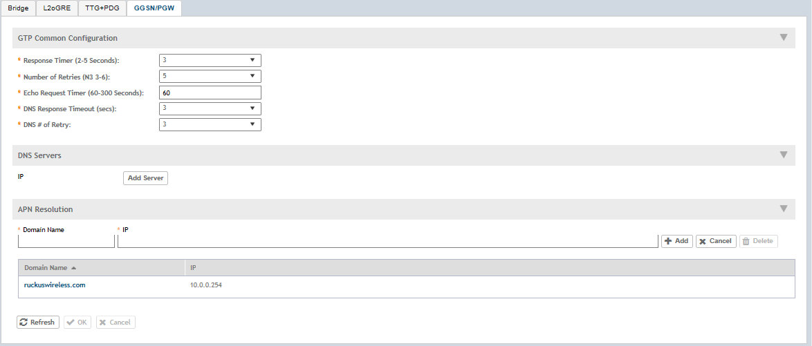
  1. Go to Services & Profiles > Core Network Tunnel.
  2. Select the GGSN/PGW tab.
    The GGSN/PGW page appears.
    Figure 149  GGSN/PGW

  3. Configure the following:
    1. GTP Common Configuration
      1. Response Timer: Define the response expected from GGN server from the drop down list, which ranges from 2 to 5 seconds. The controller will attempt to contact the GGSN during call establishment.
      2. Number of Retries: Define the number of times that controller will attempt to contact the GGSN. If all attempts fail, the relevant alarm is raised to confirm the failure of the GGSN path. For example, if the response timer is 3 and the number of retries is 5, it means that for each retry, controller will for 3 seconds.
      3. Echo Request Timer: Define number of seconds that the GGSN waits before sending an echo-request message to check for GTP path failure.
      4. DNS Response Timeout: Specify the maximum time that DNS waits for a response from a signaling request message.
      5. DNS # Retry: specify the maximum number of times that the DNS attempts to send a signaling request.
    2. DNS Servers: Click Add Server to add a DNS IP address. If you’re adding multiple DNS IP addresses, you can set their priority by clicking the Move Up and Move Down buttons. DNS servers that are higher up on the list of servers are given higher priority.
    3. APN Resolution: Type the GGSN Domain Name and IP address and click Add.
  4. Click OK. You have configuring the GGSN/PGW Service