Creating Switch Level Configuration
You can configure switch, ACL, VLAN, and static route settings for each switch.
-
Click
Configure and select the
Switch tab.
Configure the following switch details:Figure 74 Switch Configuration
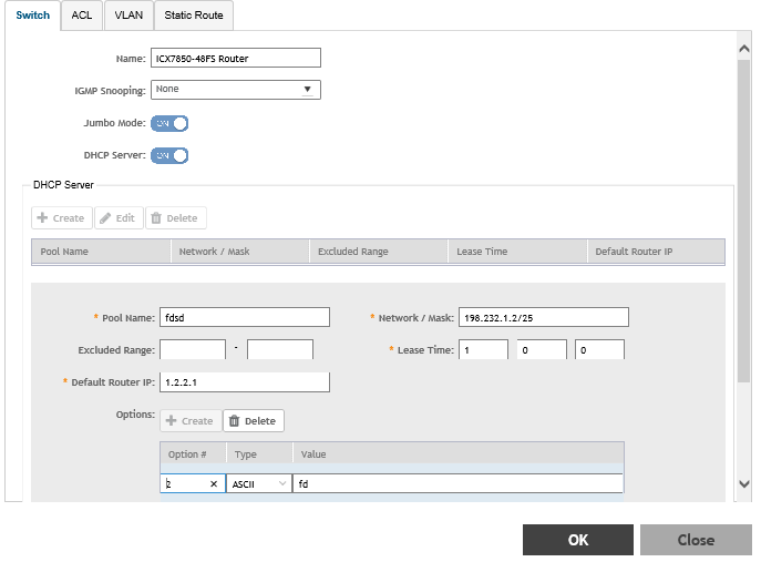
- Name: Enter the name of the switch.
- IGMP Snooping: Select the profile from the list.
- Jumbo Mode: Enabling this option to reboot the switch.
- DHCP Server: Enable this option and click
Create to configure the following DHCP server settings:.
NOTEYou must disable the DHCP client before enabling the DHCP server.
- Click
Create and update the following:
- Pool Name: Enter a name.
- Network/Mask: Enter the network address and network mask.
- Excluded Range: Enter the network range to be excluded.
- Lease Time: Enter the lease time duration.
- Default Router IP: Enter the default router IP address.
- Options: Click
Create and enter the
Option #,
Type, and
Value.
Click Update to apply the option.
- Click OK to add the newly created switch configuration to the Switch page. You can edit or delete the configuration by selecting Configure or Delete, respectively.
-
Select the
ACL tab.
Figure 75 ACL Configuration
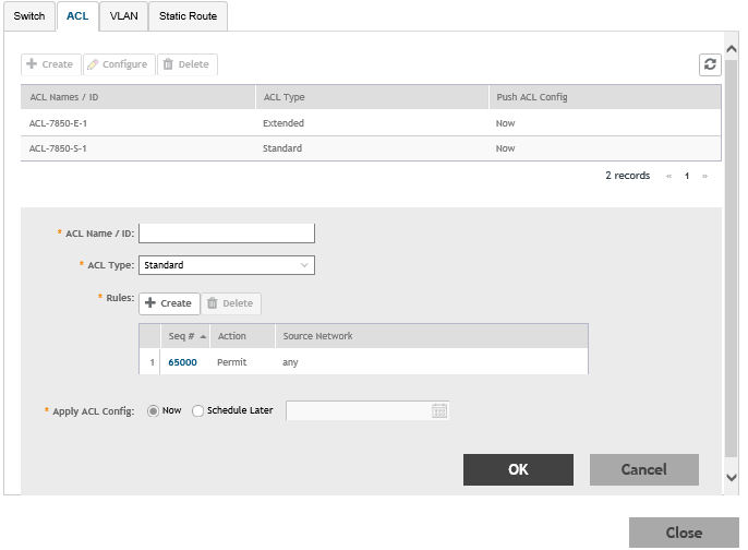
Click Create and configure the following ACL details:- ACL Name/ID: Enter the name of the access control list or provide the list ID.
- ACL Type:: Select Standard or Extended from the list.
- Rules: Click Create to create an ACL rule. You must provide the list sequence (Seq#), Action (Permit or Deny), and Source Network information to create the rule.
- Apply ACL Config:Select Now or Schedule Later. If you choose to schedule the configuration deployment for later, provide the time and date.
- Click OK to add the newly created ACL configuration to the ACL page. You can edit or delete the configuration by selecting Configure or Delete, respectively.
-
Select the
VLAN tab.
Figure 76 VLAN Configuration
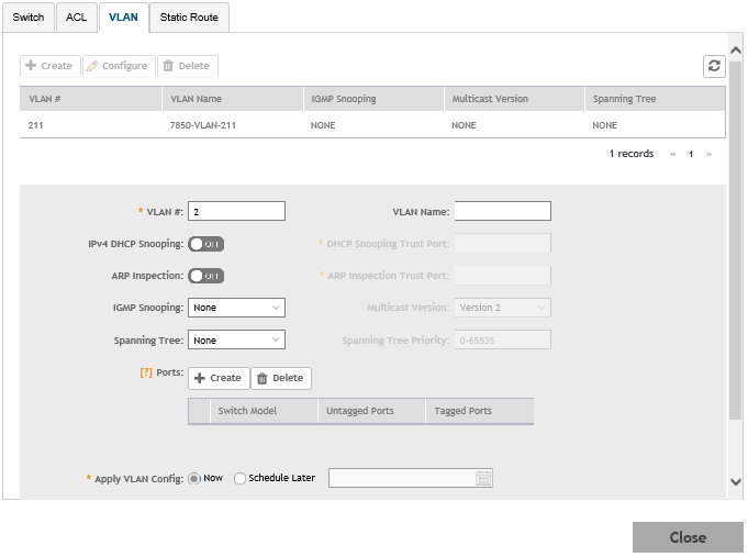 Click Create and configure the following VLAN details:
- VLAN #: Enter the number of the VLAN.
- VLAN Name: Enter the name of the Layer 2 VLAN.
- IPv4 DHCP Snooping: Enable or disable IPv4 DHCP Snooping. Enabling this option allows the controller to send the ACL-per-port-per-VLAN message to the switch to reboot it. If you enable IPv4 DHCP Snooping, you must provide the trusted port for this option in the DHCP Snooping Trust Port field.
- APR Inspection: enable or disable ARP Inspection. Enabling this option allows the controller to send the ACL-per-port-per-vlan message to the switch to reboot it. If you enable IPv4 DHCP Snooping, you must provide the trusted port for this option in the ARP Inspection Trust Port field.
- IGMP Snooping: Select None, Active, or Passive from the list. The Internet Group Management Protocol (IGMP) allows the switch to track the communication between hosts and routers based on which the switch maintains a map of which links need which IP multicast streams. If you select Active or Passive, you are required to select the Multicast Version as well.
- Spanning Tree: Select None, STP (802.1d), or RSTP (802.1w) from the list. Both Spanning Tree Protocol (STP) and Rapid Spanning Tree Protocol (RSTP) prevent creation of bridge loops when you have redundant paths in your network, and the broadcast radiation that results from them. If you select STP or RSTP, you are required to select the Spanning Tree Priority as well.
- Ports: Click Create to assign the ports to the switch model. Type values for Switch Model, Untagged Ports, and Tagged Ports and click Update.
- Apply VLAN Config: Select Now or Schedule Later. If you choose to schedule the configuration deployment for later, provide the time and date.
- Click OK to add the newly created VLAN configuration to the VLAN page. You can edit or delete the configuration by selecting Configure or Delete, respectively.
-
Select the
Static Route tab.
Figure 77 Static Route Configuration
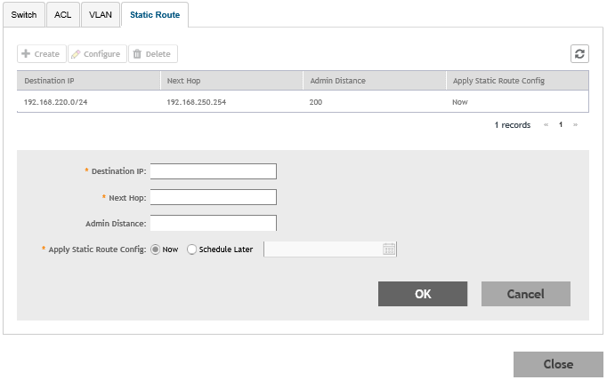
Click Create and configure the following static route details:- Destination IP: Enter the destination IP address.
- Next Hop: Enter the next hop IP address. Multicast and broadcast IP addresses are not allowed.
- Admin Distance: Enter a value from 1 through 255.
- Apply Static Route Config, Select Now or Schedule Later. If you choose to schedule the configuration deployment for later, provide the time and date.
- Click OK to add the newly created static route configuration to the Static Route page. You can edit or delete the configuration by selecting Configure or Delete, respectively.