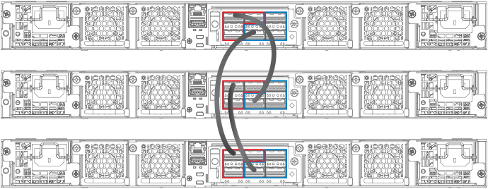
Using secure-setup to configure a traditional stack in a ring topology
The following figure shows three ICX 7750 stacking units connected in a ring. The secure-setup example that follows is for 12 ICX 7750 units in a ring topology. However, the procedure can be used for any stackable ICX device and any size traditional stack.
- Connect the devices using the stacking ports and stack cabling. For more information, refer to the appropriate hardware installation guides.
- Power on the units.
- Connect your console to the intended active controller. The unit through which you run secure-setup becomes the active controller by default.
-
Issue the
stack enable command on the intended active controller.
device# configure terminal
device(config)# stack enable
device(config)# exit
-
Enter the
stack secure-setup command. As shown in the following example, this command triggers a
Ruckus proprietary discovery protocol that begins the discovery process in both upstream and downstream directions. The discovery process produces a list of upstream and downstream devices that are available to join the stack. Secure-setup can detect up to 11 units in each direction (22 units total); however, you must select a total number of units that is less than the maximum stack size for the device because the controller is also part of the stack.
The following example shows the suggested discovered topology.NOTEDuring the secure-setup process, after one minute of inactivity, authentication for stack members expires, forcing you to restart the process.NOTETo exit the secure-setup, enter ^C at any time.
ICX7750-48F Router# stack secure-setup
ICX7750-48F Router# Discovering the stack topology...

Current Discovered Topology - RING

Available UPSTREAM units
Hop(s)  Id      Type          Mac Address
 1       new  ICX7750-48XGF   cc4e.246d.8d80
 2       new  ICX7750-48XGF   cc4e.246d.9b00
 3       new  ICX7750-48XGF   cc4e.246d.9c80
 4       new  ICX7750-20QXG   cc4e.2439.2a80
 5       new  ICX7750-20QXG   cc4e.2439.3700
 6       new  ICX7750-20QXG   cc4e.2439.3880
 7       new  ICX7750-20QXG   cc4e.2439.2d00
 8       new  ICX7750-48XGC   cc4e.2439.1a00
 9       new  ICX7750-48XGC   cc4e.2439.1680
10       new  ICX7750-48XGC   cc4e.2439.1d80
11       new  ICX7750-48XGC   cc4e.2439.1280

Available DOWNSTREAM units
Hop(s)  Id      Type          Mac Address
 1       new  ICX7750-48XGC   cc4e.2439.1280
 2       new  ICX7750-48XGC   cc4e.2439.1d80
 3       new  ICX7750-48XGC   cc4e.2439.1680
 4       new  ICX7750-48XGC   cc4e.2439.1a00
 5       new  ICX7750-20QXG   cc4e.2439.2d00
 6       new  ICX7750-20QXG   cc4e.2439.3880
 7       new  ICX7750-20QXG   cc4e.2439.3700
 8       new  ICX7750-20QXG   cc4e.2439.2a80
 9       new  ICX7750-48XGF   cc4e.246d.9c80
10       new  ICX7750-48XGF   cc4e.246d.9b00
11       new  ICX7750-48XGF   cc4e.246d.8d80

Do you accept the topology (RING) (y/n)?: y
You are prompted to accept the topology. -
Enter
y to accept the topology. You should see output similar to the following.
Selected Topology: Active Id Type Mac Address 1 ICX7750-48XGF cc4e.246d.9e00 Selected UPSTREAM units Hop(s) Id Type Mac Address 1 2 ICX7750-48XGF cc4e.246d.8d80 2 3 ICX7750-48XGF cc4e.246d.9b00 3 4 ICX7750-48XGF cc4e.246d.9c80 4 5 ICX7750-20QXG cc4e.2439.2a80 5 6 ICX7750-20QXG cc4e.2439.3700 6 7 ICX7750-20QXG cc4e.2439.3880 7 8 ICX7750-20QXG cc4e.2439.2d00 8 9 ICX7750-48XGC cc4e.2439.1a00 9 10 ICX7750-48XGC cc4e.2439.1680 10 11 ICX7750-48XGC cc4e.2439.1d80 11 12 ICX7750-48XGC cc4e.2439.1280 Selected DOWNSTREAM units Hop(s) Id Type Mac Address 1 12 ICX7750-48XGC cc4e.2439.1280 2 11 ICX7750-48XGC cc4e.2439.1d80 3 10 ICX7750-48XGC cc4e.2439.1680 4 9 ICX7750-48XGC cc4e.2439.1a00 5 8 ICX7750-20QXG cc4e.2439.2d00 6 7 ICX7750-20QXG cc4e.2439.3880 7 6 ICX7750-20QXG cc4e.2439.3700 8 5 ICX7750-20QXG cc4e.2439.2a80 9 4 ICX7750-48XGF cc4e.246d.9c80 10 3 ICX7750-48XGF cc4e.246d.9b00 11 2 ICX7750-48XGF cc4e.246d.8d80 -
If the Brocade device supports stacking trunks, the system next displays available trunk options in turn and requests your input on how many ports to include. The range is presented in parentheses, and the current setting is presented in square brackets. For example, (1-3) [ 1 ] indicates that the current connection is a single-port link, and you have the option of electing a 2-port or a 3-port trunk instead. When prompted, enter the desired trunk size as shown in the following example.
Confirm Stacking Links...

UPSTREAM Unit: Id new at 4 hop(s) ICX7750-20QXG cc4e.2439.2a80

Enter the desired links(1-3)[1]: 3

UPSTREAM Unit: Id new at 6 hop(s) ICX7750-20QXG cc4e.2439.3880

Enter the desired links(1-3)[1]: 3

UPSTREAM Unit: Id new at 10 hop(s) ICX7750-48XGC cc4e.2439.1d80

Enter the desired links(1-2)[1]: 2

UPSTREAM Unit: Id new at 11 hop(s) ICX7750-48XGC cc4e.2439.1280

Enter the desired links(1-2)[1]: 2
Once you have specified trunk sizes, you should see system output similar to the following example, and you are prompted to confirm the stack unit IDs.Selected Topology: Active Id Type Mac Address 1 ICX7750-48XGF cc4e.246d.9e00 Selected UPSTREAM units Hop(s) Id Type Mac Address 1 2 ICX7750-48XGF cc4e.246d.8d80 2 3 ICX7750-48XGF cc4e.246d.9b00 3 4 ICX7750-48XGF cc4e.246d.9c80 4 5 ICX7750-20QXG cc4e.2439.2a80 5 6 ICX7750-20QXG cc4e.2439.3700 6 7 ICX7750-20QXG cc4e.2439.3880 7 8 ICX7750-20QXG cc4e.2439.2d00 8 9 ICX7750-48XGC cc4e.2439.1a00 9 10 ICX7750-48XGC cc4e.2439.1680 10 11 ICX7750-48XGC cc4e.2439.1d80 11 12 ICX7750-48XGC cc4e.2439.1280 Selected DOWNSTREAM units Hop(s) Id Type Mac Address 1 12 ICX7750-48XGC cc4e.2439.1280 2 11 ICX7750-48XGC cc4e.2439.1d80 3 10 ICX7750-48XGC cc4e.2439.1680 4 9 ICX7750-48XGC cc4e.2439.1a00 5 8 ICX7750-20QXG cc4e.2439.2d00 6 7 ICX7750-20QXG cc4e.2439.3880 7 6 ICX7750-20QXG cc4e.2439.3700 8 5 ICX7750-20QXG cc4e.2439.2a80 9 4 ICX7750-48XGF cc4e.246d.9c80 10 3 ICX7750-48XGF cc4e.246d.9b00 11 2 ICX7750-48XGF cc4e.246d.8d80 Do you accept the unit id's (y/n)?: y -
Review the topology and the unit IDs that are displayed. When prompted, enter
y if you want to accept the assigned unit IDs.
NOTEYou can also enter n to decline the assigned unit IDs. The system then prompts you to enter different IDs, warns that changing the unit IDs manually may modify stack configuration, and recommends that you save the configuration and reload it after the stack is ready.
-
The active controller automatically checks all prospective stack members to see if they are password-protected. If a unit is password- protected, enter the password before you to add the unit. If you do not know the password, take one of the following actions:
- Discontinue secure-setup by entering ^C.
- Obtain the device password from the administrator.
- Skip this unit and continue the secure-setup for your stack. The password-protected device and all devices connected behind it will not be included in the setup process.
In the following example, the second unit is password-protected, so you are asked for the password.
device# stack secure-setup
device# Discovering the stack topology...
Verifying password for the password protected units...
Found UPSTREAM units
Hop(s)  Id   Type            MAC Address
1       2    ICX7750-48XGF   cc4e.246d.8d80
2       3    ICX7750-48XGF   cc4e.246d.9b00


Enter password for ICX7750-48XGF located at 2 hop(s): ****
Enter the number of the desired UPSTREAM units (1-2)[1]: 2
Selected Topology:
Active  Id   Type            MAC Address
        1    ICX7750-48XGF   cc4e.246d.9e00
Selected UPSTREAM units
Hop(s)  Id   Type            MAC Address
1       2    ICX7750-48XGF   cc4e.246d.8d80
2       3    ICX7750-48XGF   cc4e.246d.9b00
Do you accept the unit id's (y/n)?: y
-
Enter
y to accept these recommendations, or enter
n to reject the recommendations.
NOTEYou can use secure-setup to renumber the units in your stack. Refer to Renumbering stack units.
After you accept the unit IDs, an active controller is elected, the stack is formed, and a standby controller is designated. You should see output similar to the following example.
ICX7750-48F Router#T=18m45.7: Election, was alone --> active, ID=1, pri=128,
12U(1-12), A=u1, nbr#=11 11, reason: u6: SecureS, ,
T=18m49.7: Election, was active, no change, ID=1, pri=128, 12U(1-12), A=u1,
nbr#=11 11, reason: u1: stk-po-chg, ,
T=18m52.3: reset unit  2: u2 bo-id=1
T=18m52.3: reset unit  3: u3 bo-id=1
T=18m52.3: reset unit  5: u5 bo-id=1
T=18m52.3: reset unit  6: u6 bo-id=1
T=18m52.3: reset unit  7: u7 bo-id=1
T=18m52.3: reset unit  8: u8 bo-id=1
T=18m52.3: reset unit  9: u9 bo-id=1
T=18m52.3: reset unit 10: u10 bo-id=1
T=18m52.3: reset unit 11: u11 bo-id=1
T=18m52.3: reset unit 12: u12 bo-id=1
Reset extra units due to path: 4

Config changed due to add/del units. Do write mem if you want to keep it
T=18m55.3: Unit 1 loses all neighbors.
T=18m55.4: Active U1 deletes U2 and its config because it is learned.
T=18m55.6: Active U1 deletes U3 and its config because it is learned.
T=18m55.8: Active U1 deletes U4 and its config because it is learned.
T=18m55.9: Active U1 deletes U5 and its config because it is learned.
T=18m56.0: Active U1 deletes U6 and its config because it is learned.
T=18m56.1: Active U1 deletes U7 and its config because it is learned.
T=18m56.2: Active U1 deletes U8 and its config because it is learned.
T=18m56.3: Active U1 deletes U9 and its config because it is learned.
T=18m56.4: Active U1 deletes U10 and its config because it is learned.
T=18m56.6: Active U1 deletes U11 and its config because it is learned.
T=18m56.7: Active U1 deletes U12 and its config because it is learned.
ICX7750-48F Router# T=19m55.7: Election, was active, no change, ID=1, pri=128,
3U(1-3), A=u1, nbr#=2 0, reason: u3: port-dw, ,
T=19m55.8: Synchronize webauth files to u2
T=19m55.8: Synchronize webauth files to u3
T:19m57.1: Done hot swap: active controller u1 sets u2 to Ready.
T:19m57.1: Done hot swap: active controller u1 sets u3 to Ready.

Config changed due to add/del units. Do write mem if you want to keep it
Stack unit 2 Power supply 1 is up
Stack unit 2 Power supply 2 is down
Stack unit 3 Power supply 1 is up
Stack unit 3 Power supply 2 is down
T=20m2.4: Election, was active, no change, ID=1, pri=128, 3U(1-3), A=u1, nbr#=2 0,
reason: u1: port-up, ,
T=20m3.6: 1/2/4 goes down. delete direction 1, trigger election
T=20m7.3: Election, was active, no change, ID=1, pri=128, 12U(1-12), A=u1,
nbr#=11 11, reason: u12: port-up, ,
T=20m7.6: Synchronize webauth files to u10
T=20m7.6: Synchronize webauth files to u11
Detect stack unit 12 has different startup config flash, will synchronize it
T=20m7.6: Synchronize webauth files to u12
Detect stack unit 4 has different startup config flash, will synchronize it
T=20m7.6: Synchronize webauth files to u4
T=20m7.6: Synchronize webauth files to u5
T=20m7.6: Synchronize webauth files to u6
T=20m7.6: Synchronize webauth files to u7
T=20m7.7: Synchronize webauth files to u8
T=20m8.3: Synchronize webauth files to u9
T:20m8.8: Done hot swap: active controller u1 sets u10 to Ready.
T:20m9.0: Done hot swap: active controller u1 sets u11 to Ready.
T:20m9.3: Done hot swap: active controller u1 sets u12 to Ready.
T:20m9.9: Done hot swap: active controller u1 sets u4 to Ready.
T:20m10.2: Done hot swap: active controller u1 sets u5 to Ready.
T:20m10.5: Done hot swap: active controller u1 sets u6 to Ready.
T:20m10.9: Done hot swap: active controller u1 sets u7 to Ready.
T:20m11.4: Done hot swap: active controller u1 sets u8 to Ready.
Stack unit 12 Power supply 1 is up
Stack unit 12 Power supply 2 is down
Stack unit 10 Power supply 1 is up
Stack unit 10 Power supply 2 is down

Config changed due to add/del units. Do write mem if you want to keep it
T:20m13.1: Done hot swap: active controller u1 sets u9 to Ready.
T=20m16.9: Election, was active, no change, ID=1, pri=128, 12U(1-12), A=u1,
nbr#=11 11, reason: u1: stk-po-chg, ,

Config changed due to add/del units. Do write mem if you want to keep it

ICX7750-48F Router#T=21m16.9: Assigned unit 2 to be standby
cT=21m18.9: start running config sync to standby u2
T=21m19.3: Running config sync to standby u2 is complete
-
Enter the
show stack command to verify that all units are in the ready state.
The following show stack command output shows the resulting 12-unit ICX 7750 ring topology. All units are ready.
ICX7750-48F Router#  show stack
T=23m12.5: alone: standalone, D: dynamic cfg, S: static, A=10, B=11, C=12
ID   Type          Role    Mac Address    Pri State   Comment
1  S ICX7750-48XGF active  cc4e.246d.9e00 128 local   Ready
2  D ICX7750-48XGF standby cc4e.246d.8d80   0 remote  Ready
3  D ICX7750-48XGF member  cc4e.246d.9b00   0 remote  Ready
4  D ICX7750-48XGF member  cc4e.246d.9c80   0 remote  Ready
5  D ICX7750-20QXG member  cc4e.2439.2a80   0 remote  Ready
6  D ICX7750-20QXG member  cc4e.2439.3700   0 remote  Ready
7  D ICX7750-20QXG member  cc4e.2439.3880   0 remote  Ready
8  D ICX7750-20QXG member  cc4e.2439.2d00   0 remote  Ready
9  D ICX7750-48XGC member  cc4e.2439.1a00   0 remote  Ready
10 D ICX7750-48XGC member  cc4e.2439.1680   0 remote  Ready
11 D ICX7750-48XGC member  cc4e.2439.1d80   0 remote  Ready
12 D ICX7750-48XGC member  cc4e.2439.1280   0 remote  Ready

    active
     +---+        +---+        +---+        +---+        +---+        +---+
 -2/1| 1 |2/4--2/1| C |2/4==2/1| B |2/4==2/1| A |2/4--2/1| 9 |2/4--2/1| 8 |2/4-
 |   +---+        +---+        +---+        +---+        +---+        +---+   |
 |                                                                            |
 |  standby                                                                   |
 |   +---+        +---+        +---+        +---+        +---+        +---+   |
 -2/4| 2 |2/1--2/4| 3 |2/1--2/4| 4 |2/1==2/4| 5 |2/1--2/4| 6 |2/1==2/4| 7 |2/1-
     +---+        +---+        +---+        +---+        +---+        +---+
Standby u2 - protocols ready, can failover
Current stack management MAC is cc4e.246d.9e00
For ICX devices, an equal sign (=) is used to indicate connections between trunk ports as shown in the previous example.
NOTEIn the previous example, D indicates a dynamic configuration. After you perform a write memory, the D changes to an S, for static configuration. -
If you need additional information on individual ports, enter the
show stack stack-ports command as shown in the following example.
device# show stack stack-ports active +-+ +-+ +-+ +-+ +-+ +-+ =2/1|4|2/6==2/6|3|2/1==2/1|2|2/6==2/6|1|2/1==2/1|7|2/6==2/6|6|2/1= | +-+ +-+ +-+ +-+ +-+ +-+ | | | | standby | | +-+ | --------------------------------------------------------2/1|5|2/6= +-+ U# Stack-port1 Stack-port2 1 up (1/2/1-1/2/5) up (1/2/6-1/2/10) up ports: 1/2/1, 1/2/2, 1/2/3, 1/2/4, 1/2/5 U# Stack-port1 Stack-port2 1 up (1/2/1-1/2/5) up (1/2/6-1/2/10) up ports: 1/2/1, 1/2/2, 1/2/3, 1/2/4, 1/2/5 up ports: 1/2/6, 1/2/7, 1/2/8, 1/2/9, 1/2/10 2 up (2/2/1-2/2/5) up (2/2/6-2/2/10) up ports: 2/2/1, 2/2/2, 2/2/3, 2/2/4, 2/2/5 up ports: 2/2/6, 2/2/7, 2/2/8, 2/2/9, 2/2/10 3 up (3/2/1-3/2/5) up (3/2/6-3/2/10) up ports: 3/2/1, 3/2/2, 3/2/3, 3/2/4, 3/2/5 up ports: 3/2/6, 3/2/7, 3/2/8, 3/2/9, 3/2/10 4 up (4/2/1-4/2/5) up (4/2/6-4/2/10) up ports: 4/2/1, 4/2/2, 4/2/3, 4/2/4, 4/2/5 up ports: 4/2/6, 4/2/7, 4/2/8, 4/2/9, 4/2/10 5 up (5/2/1-5/2/5) up (5/2/6-5/2/10) up ports: 5/2/1, 5/2/2, 5/2/3, 5/2/4, 5/2/5 up ports: 5/2/6, 5/2/7, 5/2/8, 5/2/9, 5/2/10 6 up (6/2/1-6/2/5) up (6/2/6-6/2/10) up ports: 6/2/1, 6/2/2, 6/2/3, 6/2/4, 6/2/5 up ports: 6/2/6, 6/2/7, 6/2/8, 6/2/9, 6/2/10 7 up (7/2/1-7/2/5) up (7/2/6-7/2/10) up ports: 7/2/1, 7/2/2, 7/2/3, 7/2/4, 7/2/5 up ports: 7/2/6, 7/2/7, 7/2/8, 7/2/9, 7/2/10 -
Once all of the stack units are active, enter the
write memory command on the active controller. This command initiates configuration synchronization, which copies the configuration file of the active controller to the rest of the stack units.
NOTEThe secure-setup process may modify your configuration with information about new units, stacking ports, and so on. For this reason, it is very important to save this information by issuing the write memory command. If you do not do this, you may lose your configuration information the next time the stack reboots.
The secure-setup process for your stack is now complete.